Showing posts with label Industrial CNC Router. Show all posts

Tuesday, December 30, 2014

Finding Your Parallel Port Address for PCI Card


If you are unable to find a computer with a parallel port to control your Industrial CNC Router and decide to install a new PCI card, you may have trouble getting Mach to communicate with the machine. First of all you want to make sure that your card is putting out a 5V signal, as some models put out lower voltage which won't work. Of course you want to make sure you follow the manufacturers instructions, including installing the appropriate driver.

You'll also want to make sure that you have Mach 3 set to find your new card. If you open Mach and Look in Config/Ports and Pins. By default Mach will assign 0x378, which is where a native parallel port would be.


 A new card is not likely to have this address, so you'll have to find out what it is.  You can find it by going to your Windows Control Panel. Clack on "Hardware and Sound"  and you should see an option for "Device Manager" Clicking on this will give you a list of your devices, including your PCI Card. Right Click on the PCI Card in the list and choose "Properties" you should see your I/O Range. Select the first four characters and enter them into Mach 3 as your port address with 0x added in front of them. Mach should now be communicate with your new PCI card.

Control panel/Hardware and Sound

Devices and Printers/Device Manager


Device Manager/PCI Parallel Port/Properties


In this case. your address would be 0xDCC8. 
Enter it into Mach 3 Config/Ports and Pins/Port Setup and Axis Selection.


Controlling your Industrial CNC Router with Newer Computer Systems

The Mach 3 software that you're using to control your Industrial CNC Router requires a 32 bit desktop version of Windows and a Native parallel port. Because these systems are getting harder to find we've done some testing with different solutions. 


If you'd like to control your machine with a laptop, a 64 bit version of windows, or a PC without a 25 pin parallel port, you'll need an external motion controller. The best solution we've found is the SSENC-2 Ethernet SmoothStepper System from Soigeneris.


We've done extensive testing on different Windows systems and it gives consistent results every time. Unlike many external motion controls, this is a plug and play solution. The SSENC-2 is plugged into the Router via parallel port, and then connects to your computer via ethernet port (USB is also available.) Since it has it's own power supply it can even be plugged into a laptop.


They provide easy to follow step by step instructions to get you going quickly.

Take a look here:


http://www.soigeneris.com/ssenc_2_ethernet_smoothstepper_system-details.aspx

Thursday, November 21, 2013

Cutting Acrylic With Your Industrial CNC Router

Many of our customers are cutting or planning to cut Acrylic with their Industrial CNC Router. You can get a smooth finish when cutting this material, however as with most plastics, you do have to pay attention to a few factors, as it requires a little more care than cutting wood. Here are the most important factors to getting a clean cut:

1) Hold Down.
Make sure that the acrylic is held down securely. If it's not it can vibrate or flex ruining your cut altogether or marring the finish. On a T-Slot tabletop,with a sacrificial board, a few strips of double sided tape on the back side will go a long way to secure the piece. If you prefer, you can also use spray adhesives. Just make sure that the chemical properties are suitable for acrylic. A Vacuum Hold Table can make things easier, but if you're cutting pieces with a small surface area you may want to take these precautions as well.

2) Bits
When cutting Acrylic, you won't get the best result using wood cutting bits, as cutting and chip removal are much more important. We recommend using a bit designed for Acrylic cutting. Our customers typically get the best results using "O-Flute" End Mill Bits.


While you can use bits of all sizes, it's generally advisable to use the largest bit possible for your design, as this increases depth possible, stability and removal of waste material.

Make sure that your bits stay sharp, as a dull bit will not give you the edges you want.

3)Feedrate
Ideal feedrate for cutting Acrylic is typically 75-300 IPM, depending on the size of your bit. For example, an 1/8" bit work better on the low end (75-100) while a 1/2" bit would work well at 200-300. This is for the sake of the bit as much as the material.
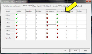
4)RPM
Recommended spindle speed for cutting Acrylic is at least 18,000 RPM. You can possibly use higher RPM's, but you may need to adjust your feedrate (faster) as well to prevent the material melting. Use these speeds as a starting point and as you bump up your feed rate and RPM, keep track of results for the best combinations.

5) Cut Depth
Aim for about twice the diameter of the bit for a uniform cut. This is also a good practice to prevent breaking your bit.

6) Ramping
In your Post Processor Program make sure to have the machine Ramp to starting point, rather than plunge straight down. This is much smoother and prevents any distortion on breaking the material surface.


Thursday, January 10, 2013

Mach Screenshots/Ports and Pins


Here are some common screenshots to double check Mach settings for you Industrial CNC Router. If your machine was working and then stopped, it is usually one of these settings that have been changed. Most of your basic settings can be found under "Config/Ports & Pins" in the title bar. I'll start with those.

This screen is the "Motor Outputs" screen, which controls the movement of each axis (X, Y and Z) You'll notice that the X, Y and Z rows are enabled. Also note the "Step Pin" and Dir Pin" columns below for the appropriate pins. Make sure "Step Low Active" is enabled. If your settings do not match you won't be able to jog your spindle.


The next important tab in Ports and Pins is "Output Signals" This controls the Spindle On/Off operation. You should only be concerned with one row, Output #1. Proper settings are below.


You should be aware of the "Input Signals Tab." This is where input from the machine to the computer is controlled and enables your limit switches and e-stop function. These functions can provide interference, and the e-stop is typically bypassed, so there's no reason to leave it on.

I would suggest disabling everything in here as you can set limits more easily with the soft limits function in the software. Note that I have none of these rows enabled and pins are set to 0.


Installing Configuration File


This post is to deal with the settings files that Industrial CNC sends to every customer; the configuration file (an .xml file)

There is no reason for you to open the file. I say this only because many people have called to say they can't open them.

Here is exactly how to deal with these files:

From the e-mail containing these files, click on the download link for the file.
Select Save, when the window comes up asking where to save it, select Desktop.

Make sure you have already gone to the Mach3 website and downloaded Mach3. Here's the link (go to downloads)
http://machsupport.com/downloads.php (scroll down and click on the "Mach 3" link under "Lockdown")

You can also purchase a license from Mach3 on the same page.

In Windows Explorer Drag the .xml file into your Main Mach3 Folder.
(to find this, right click on the windows start button and choose "Explore"
A new window will open with folders on the left side of the screen.
Find the Folder labeled "Mach3"
and double click it.)

The right side of that window will now be the inside of the Mach3 folder. Then, click the middle button in the top right corner of your screen (in between the - and x buttons, and you should see your desktop beneath that window.

Drag the two files from the desktop to the inside of the Mach3 folder.

You should now be ready to control your Industrial CNC Router!

Crop Circles


We get an occasional calls from Industrial CNC customers to tell us that the router is cutting "crop circles" This means usually perfect circles that are not included in the gcode.

This is usually from a customer using their own post processor with their own settings.

This has been solved every time I've heard of it by simply changing one option in Mach 3 under Config/General Config. Go to Motion Control, then IJ Mode and change the radio button selection.

See picture below:


Computer Requirements


In order to ensure communication with your Industrial CNC Router, the following requirements are necessary:

32-bit version of Windows 2000, Windows XP, Windows Vista, or Windows 7 Operating System

1Ghz CPU

512MB RAM

Non-integrated Video Card with 32MB RAM

Basic Computer Skills (ability to copy/rename files, browse directories, etc)

Desktop PC (if using the Mach3 Parallel Port Driver - laptops are not supported because the power saving features of the chipsets disrupt the pulse stream, PCMCIA and USB parallel adaptors will *not* work.)

Also note that it is important that your parallel port puts out 5V rather than 3.5V. This is more likely to be a problem with newer computers.

USB to parallel adapters do not work.

It is recommended that you dedicate your PC to the CNC Machine, networking, antivirus software and internet do not help and can interfere with performance.

Motor Tuning


For your Industrial CNC Router to cut accurately, the motors need to be tuned. Basically this means that every step sent from the computer to the machine needs to translate correctly to the units you measure with (inches or millimeters.) When motors are tuned properly the machine will cut the distance your job requires.

You will start out with your X and Y axis at around 2,000 steps per unit. And your Z axis at around 4,000 steps per unit. These are ballpark numbers, so some tuning is required. Fortunately Mach has an automated motor tuning feature that will make this easy. Go to the "SETTINGS" tab and you'll find it right over the RESET button.


Note: You will need either a digital movement gauge or a tape measure before going further.

Click on the SET STEPS PER UNIT button, and a pop up window will appear asking which axis you would like to calibrate.

Select an axis

Another window will then pop up asking how far you would like each axis to move.

Enter a number (inches)

Be advised that when you enter a number it will then move the spindle that distance (or what it thinks is that distance.) The longer the distance the more any inaccuracy will be noticeable, so use a large number but make sure the spindle is far enough to the the left or front that it can travel that distance.

As soon as the movement is done, another window will appear to ask you how far the machine actually moved.

Enter in the actual distance it moved. Make sure to add the diameter of your bit.

Mach will then suggest a number for your steps per unit. Accept it and Mach will automatically calibrate the axis to that setting.

You can also change the setting manually by going to Config/Motor Tuning


You can also change your travel speed here by adjusting the sliders on the bottom and right side of the chart.

Setting Your Soft Limits in Mach 3


When you're getting started, in order to make sure that your Industrial CNC Router doesn't run into the side of the table, it can be a good idea to set up limits in your Mach 3 software for safety. In this post, I'll you how to set your soft-limits, which means that the software will stop the table automatically before this occurs.

Please make sure that your motors are properly tuned before setting the limits or they won't work properly.

1) The first step is to go to CONFIG/PORTS and PINS/INPUT SIGNALS. Make sure that all of your limit switches are disabled. (a red X for each row) See below:


2)Jog your Router to its home position. (We'll call the end of the table with the inverter and cabinet the front) Jog your spindle as far as it will go to the left, front (stop at the edge of the table)and all the way up on the Z axis.

3)Select the button beneath the DRO's (Digital Read Out) marked MACHINE COORDINATES
A red border should appear around the button (see picture below)

4)Select the Vertical REF ALL HOME button to the left of the DRO. This should set all axes to 0. (see picture below)


5)Go to Config/Homing Limits. Enter in the cutting area dimensions for your Router. Make sure to use Zero as one dimension and the width/length as the other. Note that the Z axis is set opposite. See below:


6) Select the SOFT LIMITS button to the right of the MACHINE COORDINATES button. It should now be bordered in green.

7)Select MACHINE COORDINATES button again, so that the red border goes away, leaving the SOFT LIMITS button on (Green)

Your soft limits are now operational.

Friday, November 9, 2012

Sending CAD files to your CNC Router


If you're using a design program already, such as Corel, Adobe, Autocad, TurboCad, etc., you can generate designs, but can't save your files as g-code, the only language your Mach 3 Software understands to control your Industrial CNC Router.

In order to turn your files into g-code you need what's called a "post processor" a program from which you can take your Vector file, add cutting information (feedrate, cut depth, etc.) and then convert it to G-Code which the Mach 3 software understands.

I typically recommend Vectric Software for this. You can find them at http://www.vectric.com. They have user friendly programs for many purposes, with capabilities from simple cutting operations, all the way up to complex 3D designing. Vectric Cut 2D is a simple and powerful program and a perfect way to get started. Once you've mastered it, you can always upgrade to their top of the line programs, V-Carve Pro and Aspire. If you have a CAD/CAM background already you may want to start with at least V-Carve Pro.

Step by step:

1)From your design program, (Adobe, Corel, etc.) export your file as a .dxf file. (you can also use other file formats such as .eps and .ai. Be advised that using other types of files may not open up in the Vectric software.) Make sure to save the file somewhere you'll remember, like on a thumb drive.

2)Open the Vectric program and open the .dxf file into Cut2D.

3)Using the "Tooling" Menu on the Right Hand Side of the screen, add cutting information (depth, tool diameter etc.)

4)Save as a g-code file by clicking the floppy disk icon. Make sure to Select  "Mach 3 Arcs/Inch" Save the g-code (it'll be a .txt file) to your thumb drive.

5)Open the G-code .txt file in Mach 3

You are now ready to cut the file in Mach 3.